Posts by B.Ru

    Dear MichKul,

    Technically only one object should be visible after threshold.

    Since there is only one object to focus on, its storage within a 2D image including the required object features is no problem using ImageFiFo (FPGA block ram) until the next image arrives in the VA processing chain.


    Best regards,

    Dear Michul,


    When I look at you image:


    pasted-from-clipboard.png

    Here's typical image used in my application.

    I see only one object. Please correct me if there can be multiple object of interest.

    In case of multiple objects a classification is possible.


    A single* Object can be handled as single data-struct within a small 2D image.
    I would recommend to avoid 0D-Stream due to simulation limitations.


    *) a limited amound can be handled, too.

    Best regards,

    Dear Sangrae Kim,


    Thank you for this interesting issue.

    I looked into it and found a (hpoefully) nice fix to it.

    I can not get result image with 8192 pixels in our design file.

    -> TapSorting_10X_1Y_8192.va)

    I re-designed the addressing and added a dummy remove procedure using "cheap" operators.

    I removed the "expensive" DIV.


    This is how the dummy removement works:


    pasted-from-clipboard.png

    At the end of this the change to parallelism 8 makes it 8192 pixels per row.


    The mismatch between taps = 10 and paralleism 8 transporting only 8190 (mod 10) pixels was causing the 9 unwanted dummy splitters in between of the 10 taps.


    Please use the simulation to review the attached VA design (Modification B. Rudde):

    TapSorting_10X_1Y_8192_M;odification_Bjoern_Rudde.va


    Please let me know, if this solved your issue.


    Best regards,

    Hi Theo,


    In case of single 420 MB image inside a RAM module, you require at least 420 MB inside the FrameBufferRandomRead.

    For marathon 512 MB is fine.
    You can use several ones in parallel for ironman : 2 x 256 MB.

    Reason: First you write the full image into the buffer, then you can adress the readout.

    Hint: while one full(max dimension) image is occupying more than half of the RAM module no second image can be received while read-out period of previous one.


    Please be aware that the bit-depth of RAM module needs to be used by KernelElements*BitDepth*Parallelism! More details on this here: ImageBuffer, section Available Memory Space


    Best regards,

    Hello Lucy,


    The task of processing certain regions and then merging the results back into the original image sounds interesting.

    Reading all the ROIs by using ImageBufferMultiROI is a good choice, while each ROI image is handled one after the other.

    After calculations, we want to map each pixel of the reduced image back into its position in the original image, creating an image with the same dimensions as the original.

    A possible approach into this would be:

    Glue all result images together into a single image by using AppendImage and include/append at the end the full image out of ImageBufferMultiROI.


    To get independent pathes for ROI and Full image you can use InsertImage and RemoveImage in alternating combination.

    There will be a single result image that can be written into FrameBufferRandomRead.

    When the full image is within FrameBufferRandomRead you can use a valid addressing approach for FrameBufferRandomRead.


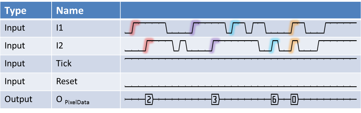
    This would be a sketch of the intended data flow:

    pasted-from-clipboard.png

    Here you can get VA Design roiProcessReplace.va

    It can be directly simulated :-)


    The VA design attached shows the data flow, while the resulting adressing is not fully implemented.
    An addtional idea for further work would be to use ImageBufferMultiROIdyn and feed the ROI-coordinates dynamically on basis of LUT, using the same details to get the final ReAddressing work. A simple RAMLut could keep all required adresses too.


    Best regards,

    Hello,


    after some detailed questions to this, I would like to share a good starting point on: "Which Signal operator to use?"


    Operator Name Short Description available since VisualApplets
    DelayToSignal.png DelayToSignal

    Delays the input signal. Delay is controlled by a input link.

    Version 1.2
    Downscale.png Downscale

    Reduces the input frequency by an adjustable factor.

    Version 1.2
    EventToSignal.png EventToSignal

    Generates a signal pulse for each input pixel with value 1.

    Version 1.2
    FrameEndToSignal.png FrameEndToSignal

    Generates a signal pulse when the end of the input image is detected.

    Version 1.2
    FrameStartToSignal.png FrameStartToSignal

    Generates a signal pulse when the start of an input image is detected.

    Version 1.2
    Generate.png Generate

    Generates a periodic signal with controllable period time.

    Version 1.2
    GetSignalStatus.png GetSignalStatus

    Obtain the current value of a signal link.

    Version 1.2
    Gnd.png Gnd

    Provides a signal with the constant value 0 (LOW).

    Version 1.2
    LimitSignalWidth.png LimitSignalWidth

    Limits the maximum pulse width of the input signal using a parameterizable maximum.

    Version 1.2
    LineEndToSignal.png LineEndToSignal

    Generates a signal pulse when the end of a input image line is detected.

    Version 1.2
    LineStartToSignal.png LineStartToSignal

    Generates a signal pulse when the start of an input image line is detected.

    Version 1.2
    PeriodToSignal.png PeriodToSignal

    Generates a periodic signal. Period time controlled by input link.

    Version 1.2
    PixelToSignal.png PixelToSignal

    Converts an image data stream into a signal stream.

    Version 1.2
    Polarity.png Polarity

    Controls the polarity of the signal (invert).

    Version 1.2
    PulseCounter.png PulseCounter

    Counts every occurrence of a one (high) at signal input link I.

    Version 1.2
    RsFlipFlop.png RsFlipFlop

    Implements a set-reset flip-flop.

    Version 1.2
    RxSignalLink.png RxSignalLink

    Receives signals from a TxSignalLink operator in the design.

    Version 2.0
    Select.png Select

    Selects a signal source from N signal sources by parameter and forward selected signal to the output.

    Version 1.2
    SetSignalStatus.png SetSignalStatus

    Set a signal link status by use of a parameter.

    Version 1.2
    ShaftEncoder.png ShaftEncoder

    Analyzes shaft encoder signal traces and outputs encoder pulses as well as the direction.

    Version 1.2
    ShaftEncoderCompensate.png ShaftEncoderCompensate

    Compensates the rewind of a shaft encoder.

    Version 1.2
    SignalDebounce.png SignalDebounce

    Suppresses fast changing signals at the input link with adjustable minimum time.

    Version 1.2
    SignalDelay.png SignalDelay

    Delays the input signal. Delay is controlled by a parameter.

    Version 1.2
    SignalEdge.png SignalEdge

    Generates a pulse of one design clock cycle, if a rising-, falling- or both- edges are detected at the input.

    Version 1.2
    SignalGate.png SignalGate

    Gates the image stream between I and O by use of a signal input.

    Version 1.2
    SignalToDelay.png SignalToDelay

    Measures and outputs the delay between two signals.

    Version 1.2
    SignalToPeriod.png SignalToPeriod

    Measures and outputs the period time of the input signal.

    Version 1.2
    SignalToPixel.png SignalToPixel

    Converts the input signal stream into a 0D pixel stream.

    Version 1.2
    SignalToWidth.png SignalToWidth

    Measures and outputs the pulse width of the input signal.

    Version 1.2
    SignalWidth.png SignalWidth

    Generates an output pulse with controllable with for rising edges at the input.

    Version 1.2
    SyncSignal.png SyncSignal

    Synchronizes a number of input links to a master signal.

    Version 1.2
    TxSignalLink.png TxSignalLink

    Sends signals to any RxSignalLink operator in the design.

    Version 2.0
    Vcc.png Vcc

    Provides a signal with the constant value 1 (HIGH).

    Version 1.2
    WidthToSignal.png WidthToSignal

    Defines the width of a pulse. Width is controlled by a input link.

    Version 1.2

    Source (10.08.2020) from Table 49. Operators of Library Signal, being part of the VA basic documentation.


    Best regards,

    Dear Jesse Lin,


    How can I find the operator JPEG_Encoder_Color_850MPs_VCL in Visual Applets ?

    Or just copy the operator by the example?

    You can find these in the user library of operators. Since these are a combination inside a protected H-box they are focused on specific bandwidth and functionality. The prot. H-Box will show properties.


    Best regards,